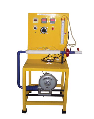
Heat Transfer in Forced Convection

Technical Details
Parameter Details
Dia & length of test section 28 (Approx.) x 40 cms.
No. of thermocouples 6 Nos.
- Nichrome heater of suitable capacity
- Blower 0.5 H.P. with motor with 12” of WGP
- Orifice & U tube manometer
Control Panel Comprising of
  • a. Dimmerstat 240 V, 2 amp,. A, C
  • b. Voltmeter 0 - 200 V., A.C.
  • c. Ammeter 0 - 200 V., A.C
  • Digital Temperature indicator 0 to 300°C with 10C least count using chromel allumel thermocouples, provided with cold junction compensation.
  • Range Of Experiment
  • To determine average surface heat transfer coefficient for a pipe losing heat by forced convection Comparison of heat transfer coefficient for different air flow rates & heat flow rates
  • To calculate Reynolds number and nusset number for each experimental conditions.